The LEDS in the Old Drobo had 4 Different uses.
-
Disk Space Leds There was 10 LEDS along the bottom of the main chassis that were used to indicate how full the drives were ( 10 - 100 % )
-
Network Activity There was one LED to indicate Network Activity
-
Power LED Lit once the unit was powered on and started.
-
Disk Activity / Faults One LED per Hard Drive on the Right Hand Side. Indicating Drive Failure or activity
Pi NAS
-
The Disk Space LEDS were able to be re-created using a Python program and 10 LEDS ( wired below )
-
The Network Activity LED is software wired to the activity triggers in the /proc file system. Its configured to the currect active port ( wifi or Ethernet )
-
The Power LED is Lit when the Network Port is activated and the Pi Boots
-
The Disk Activity LEDS are wired into the Circuit Board at the rear of the Hard Drives and is a Work In Progress to see if I can light each of the 3 leds per Hard drive.
Building the LEDS
Building the LEDs
This guide shows the step-by-step construction of the LED wiring assembly used in the Mogwai Drobo NAS project.
Step 1 – Gather the components
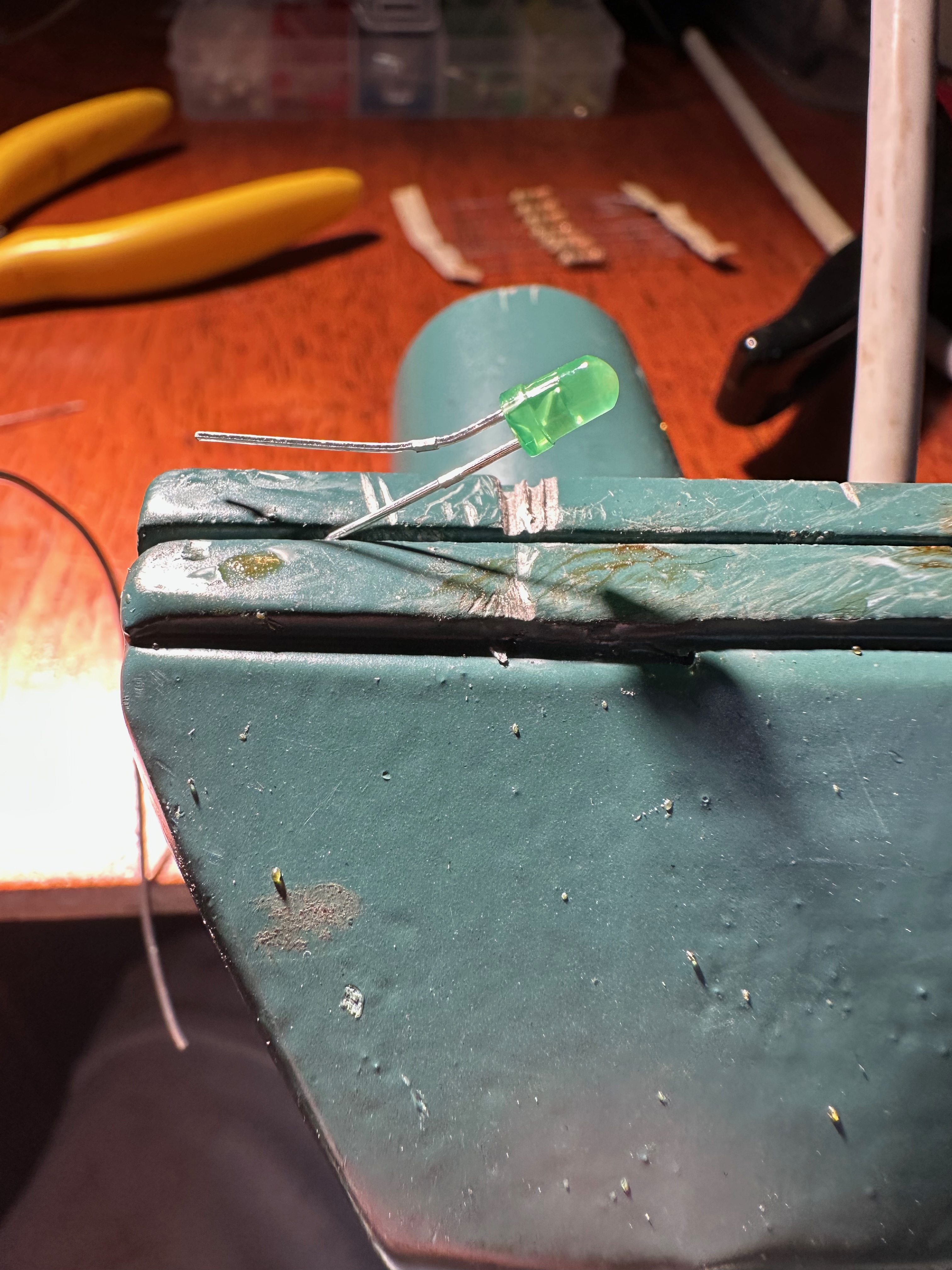
Figure 1: All of the components required for the LED assembly.
Step 2 – Prepare the LED
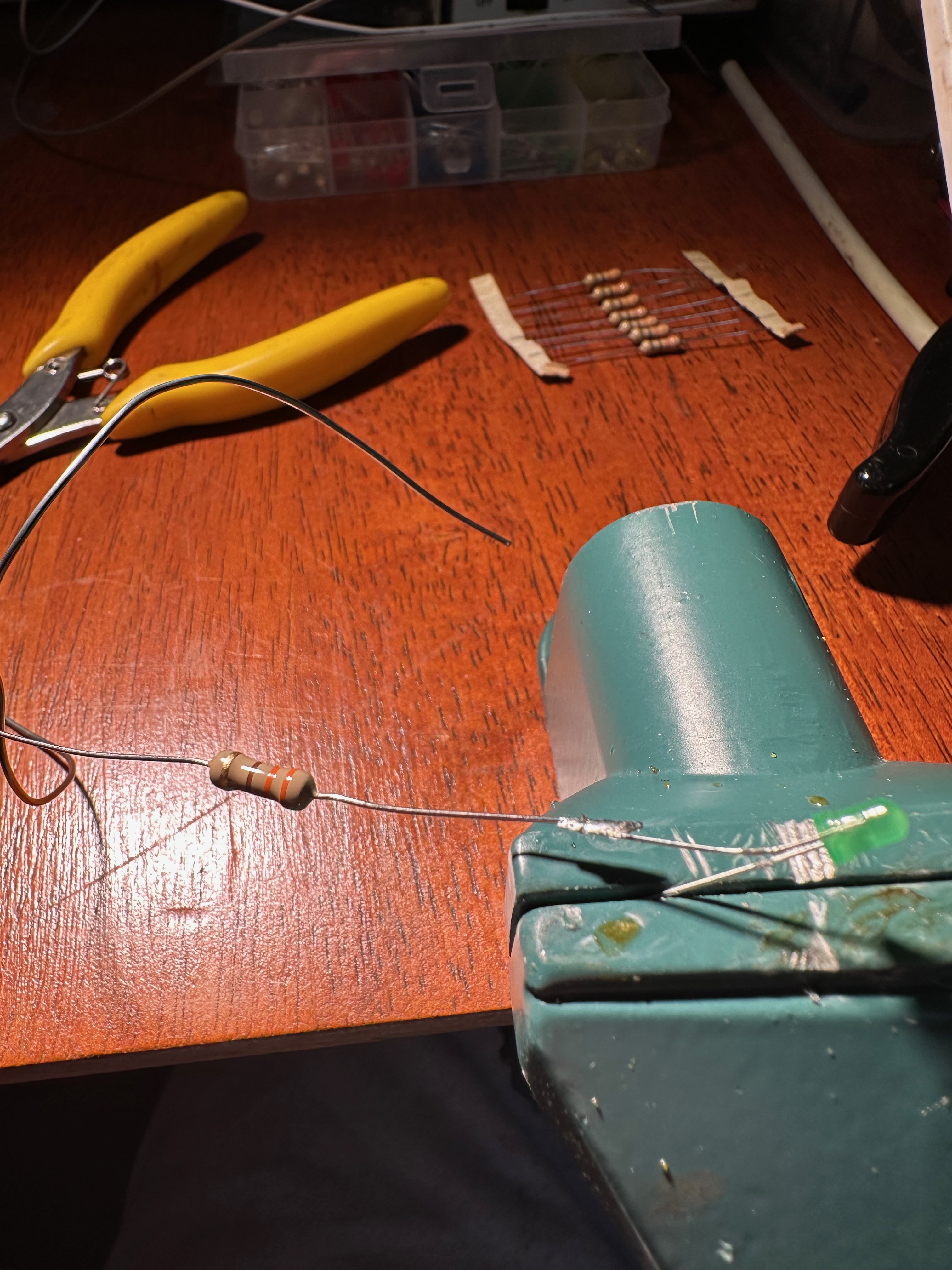
Figure 2: Prepare the LED by identifying the anode and cathode leads.
Step 3 – Fit the resistor
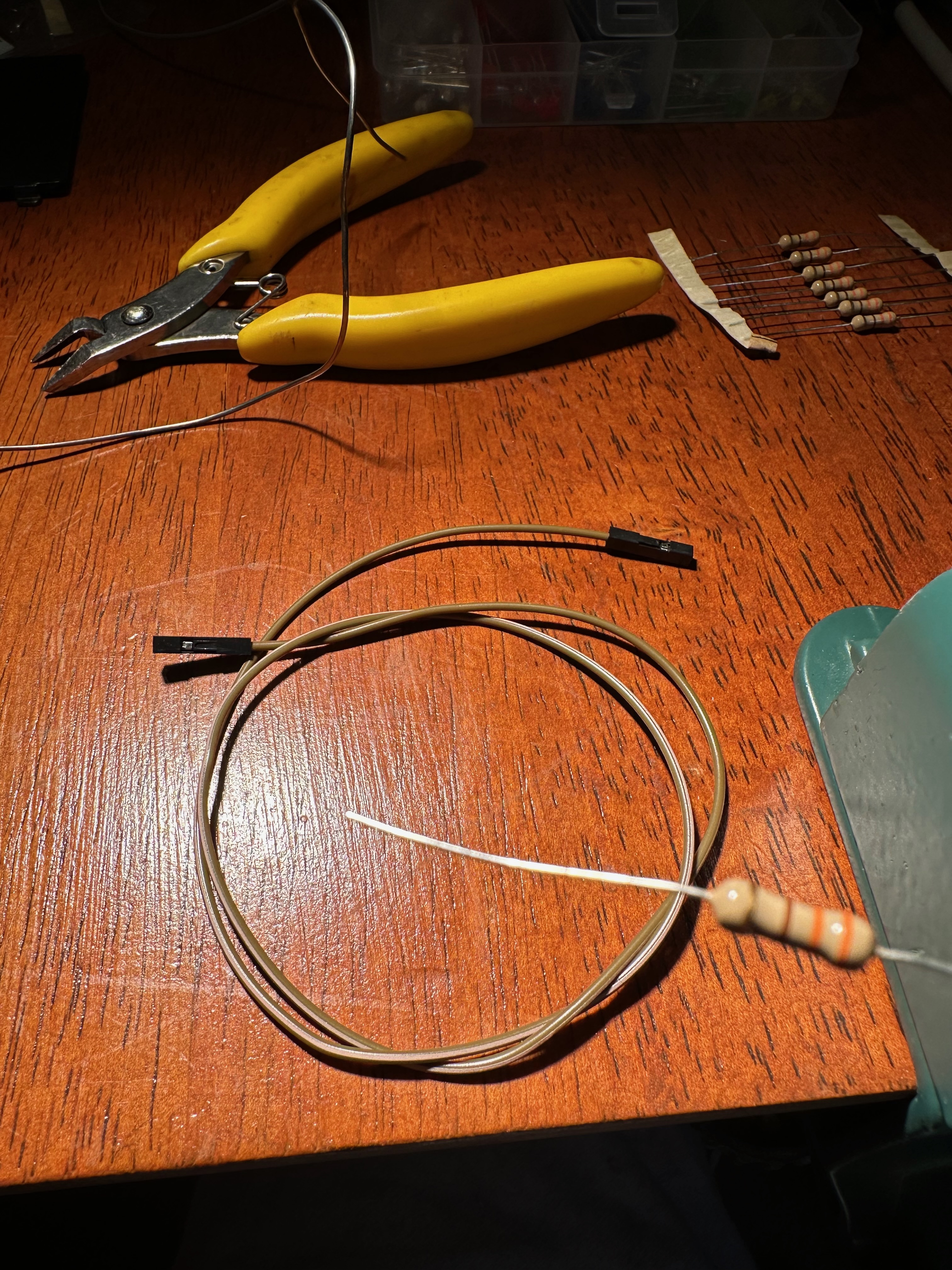
Figure 3: Position the resistor ready for soldering.
Step 4 – Solder the resistor
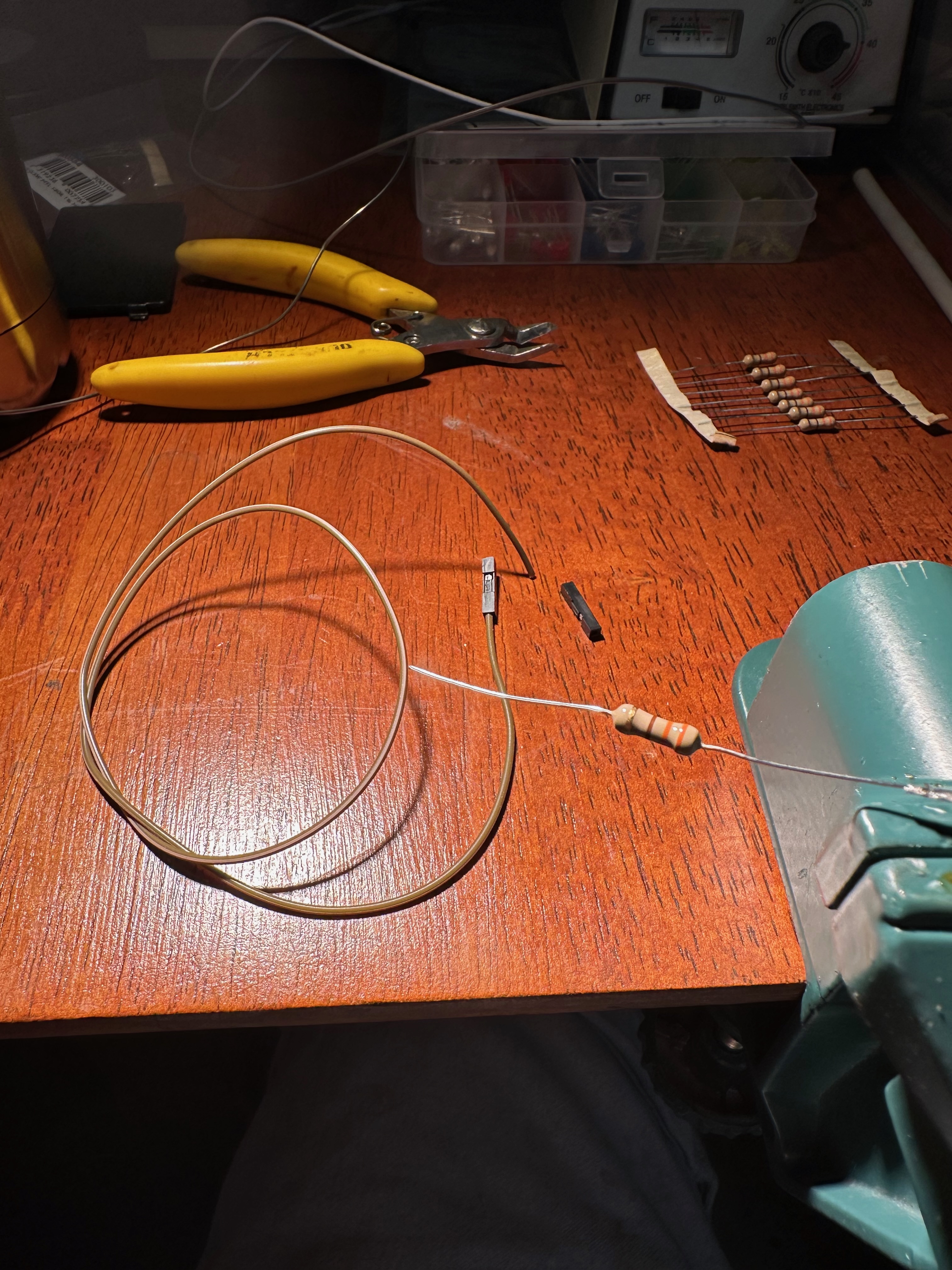
Figure 4: Solder the resistor securely to the LED lead.
Step 5 – Trim the leads
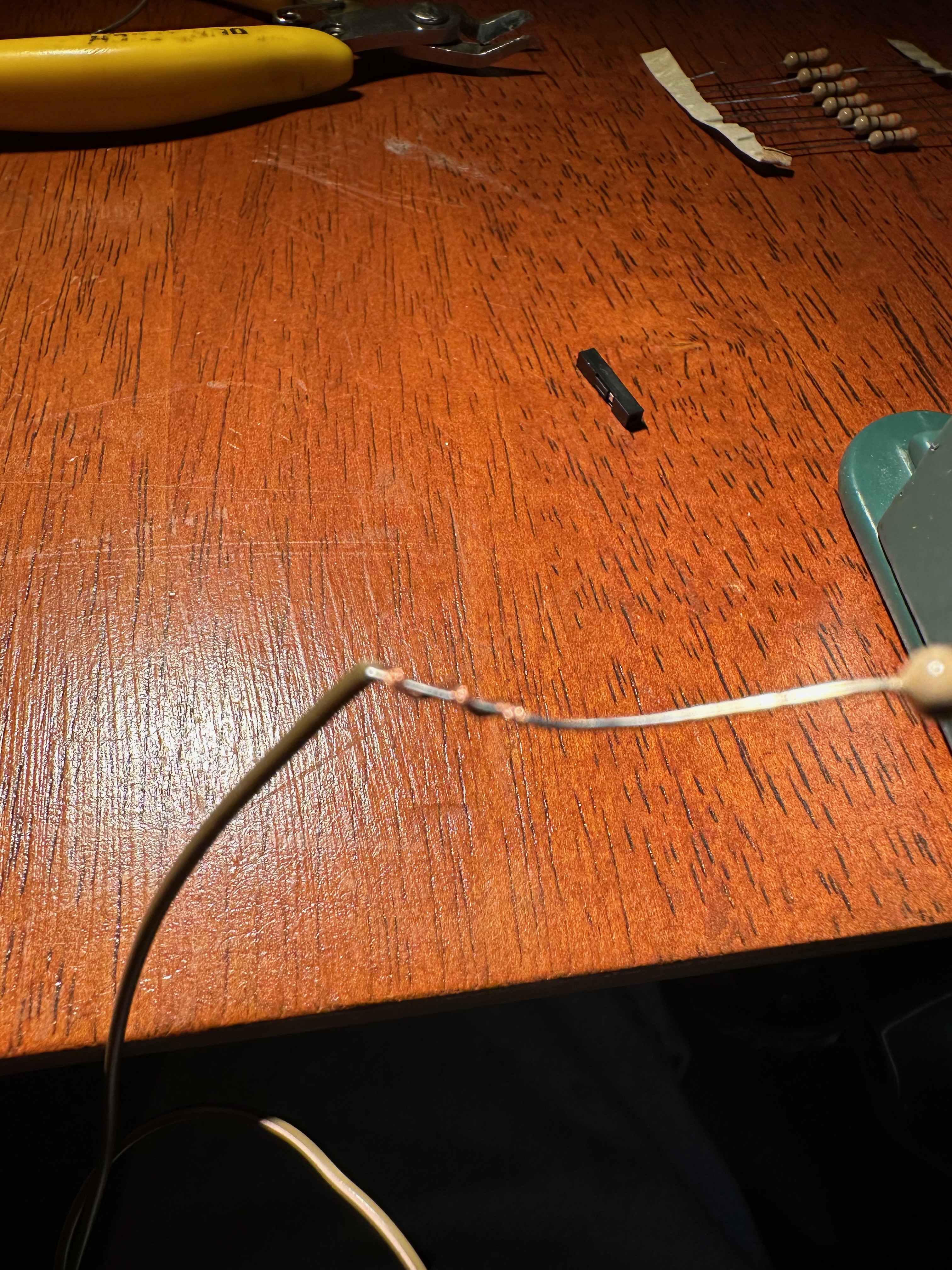
Figure 5: Trim the excess component leads after soldering.
Step 6 – Apply heat-shrink
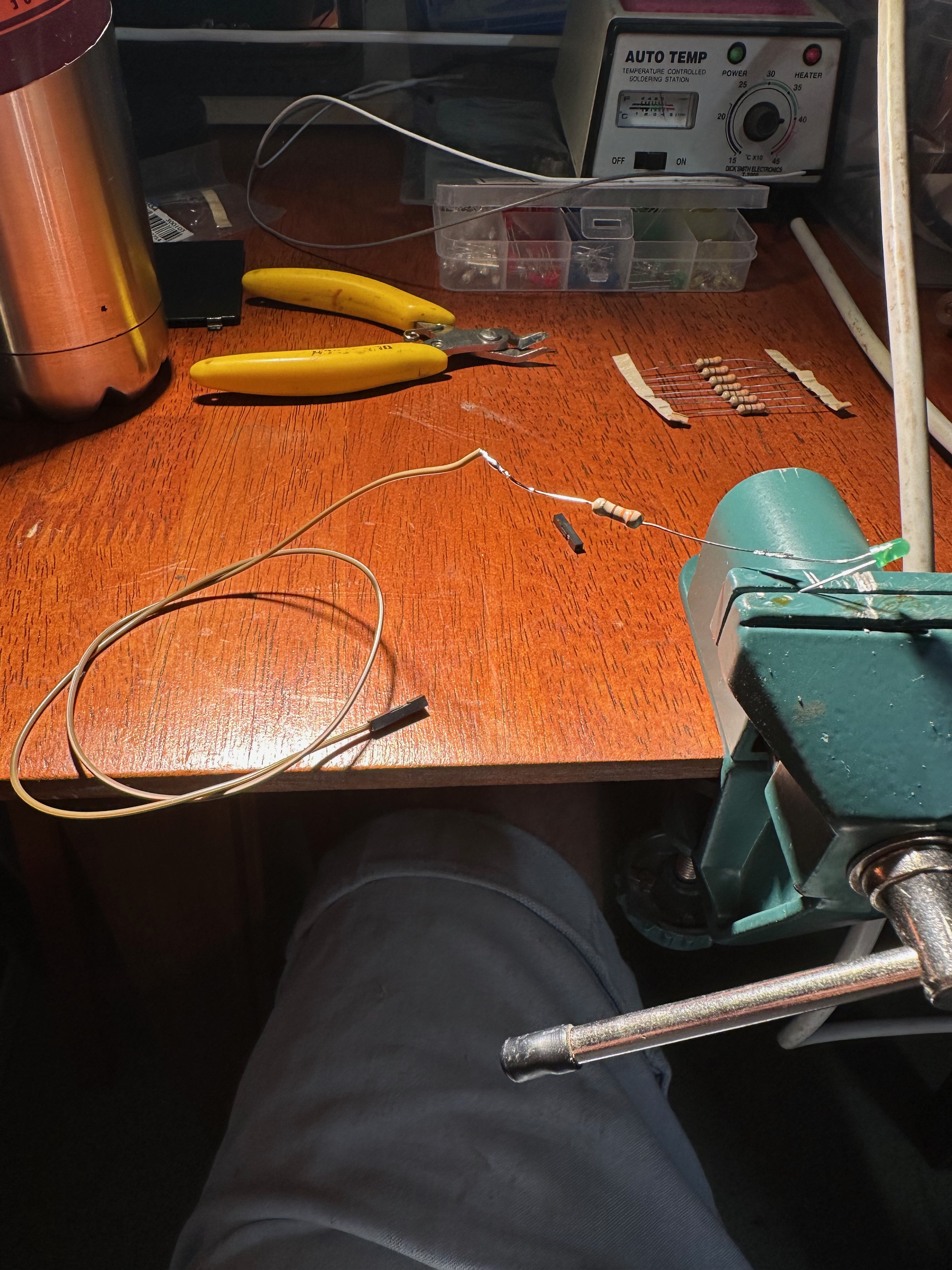
Figure 6: Slide heat-shrink tubing over the soldered joint.
Step 7 – Shrink the tubing
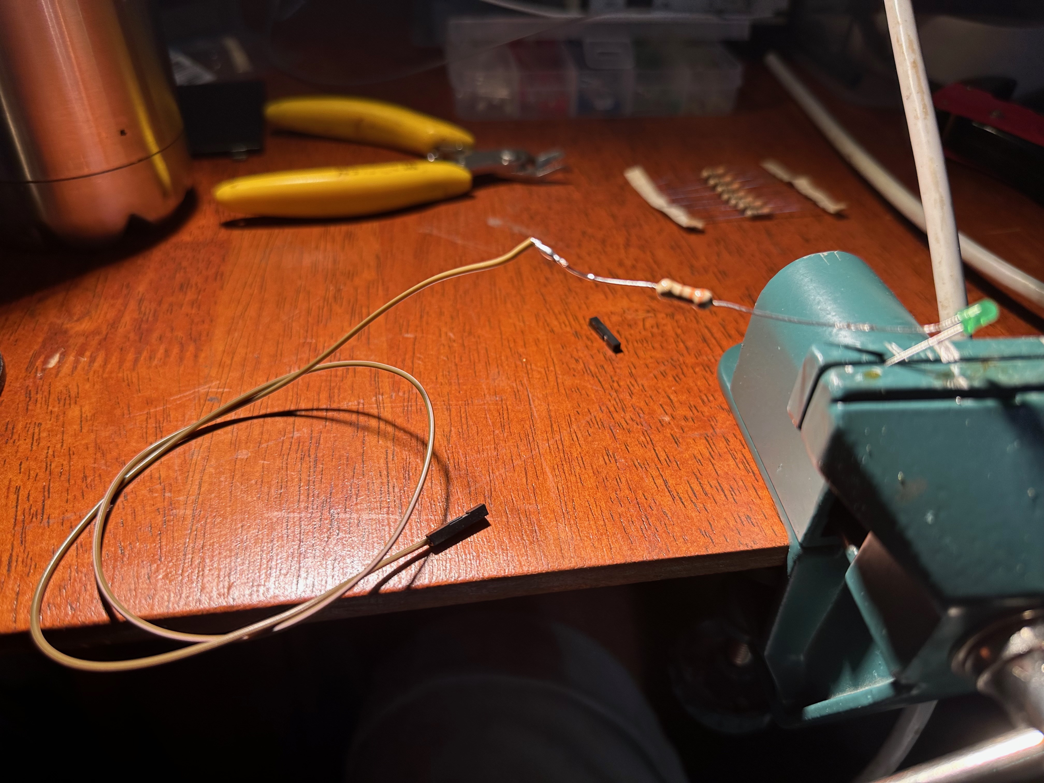
Figure 7: Apply heat to insulate and protect the solder joint.
Step 8 – Prepare the cable
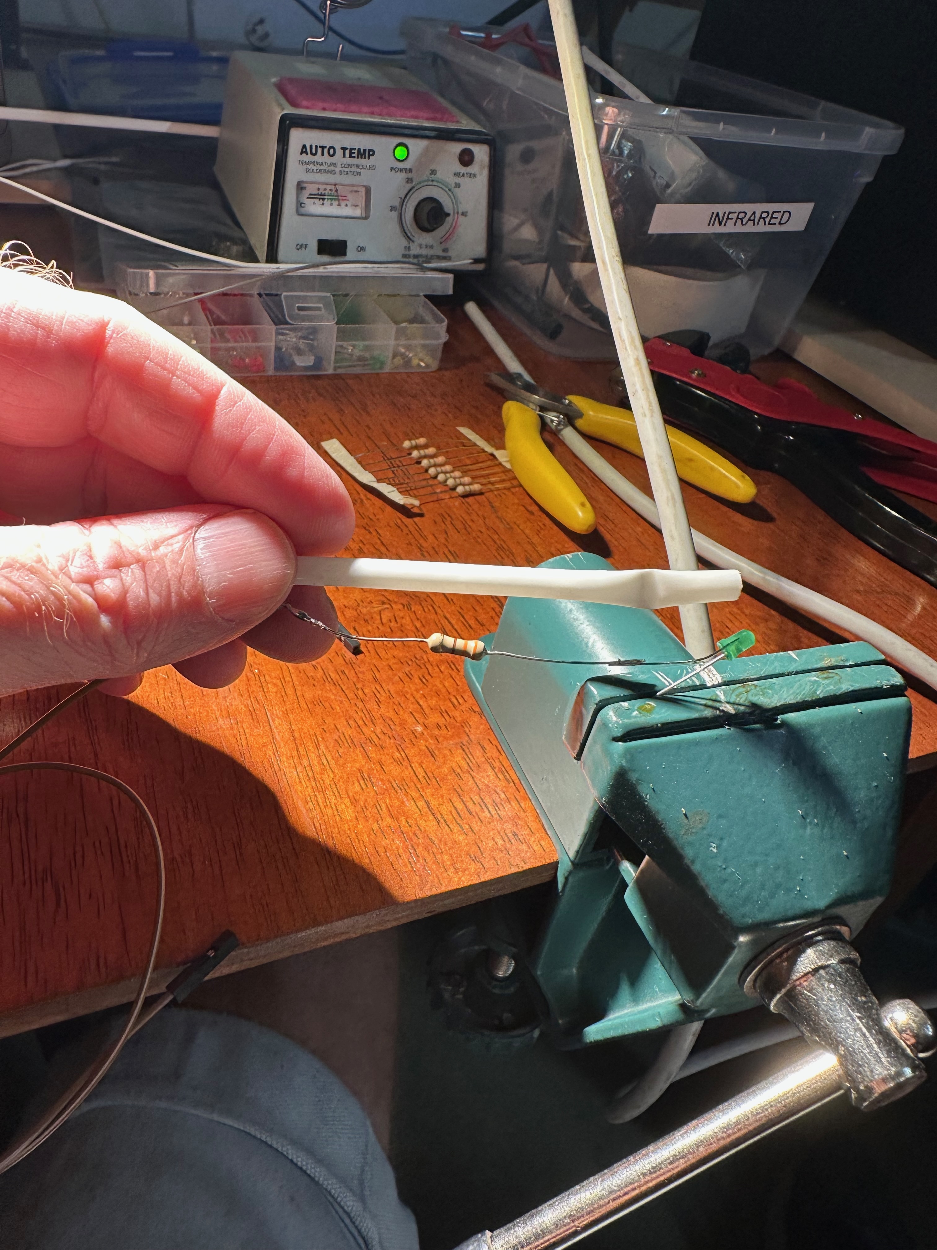
Figure 8: Strip and prepare the cable ready for connection.
Step 9 – Connect the cable
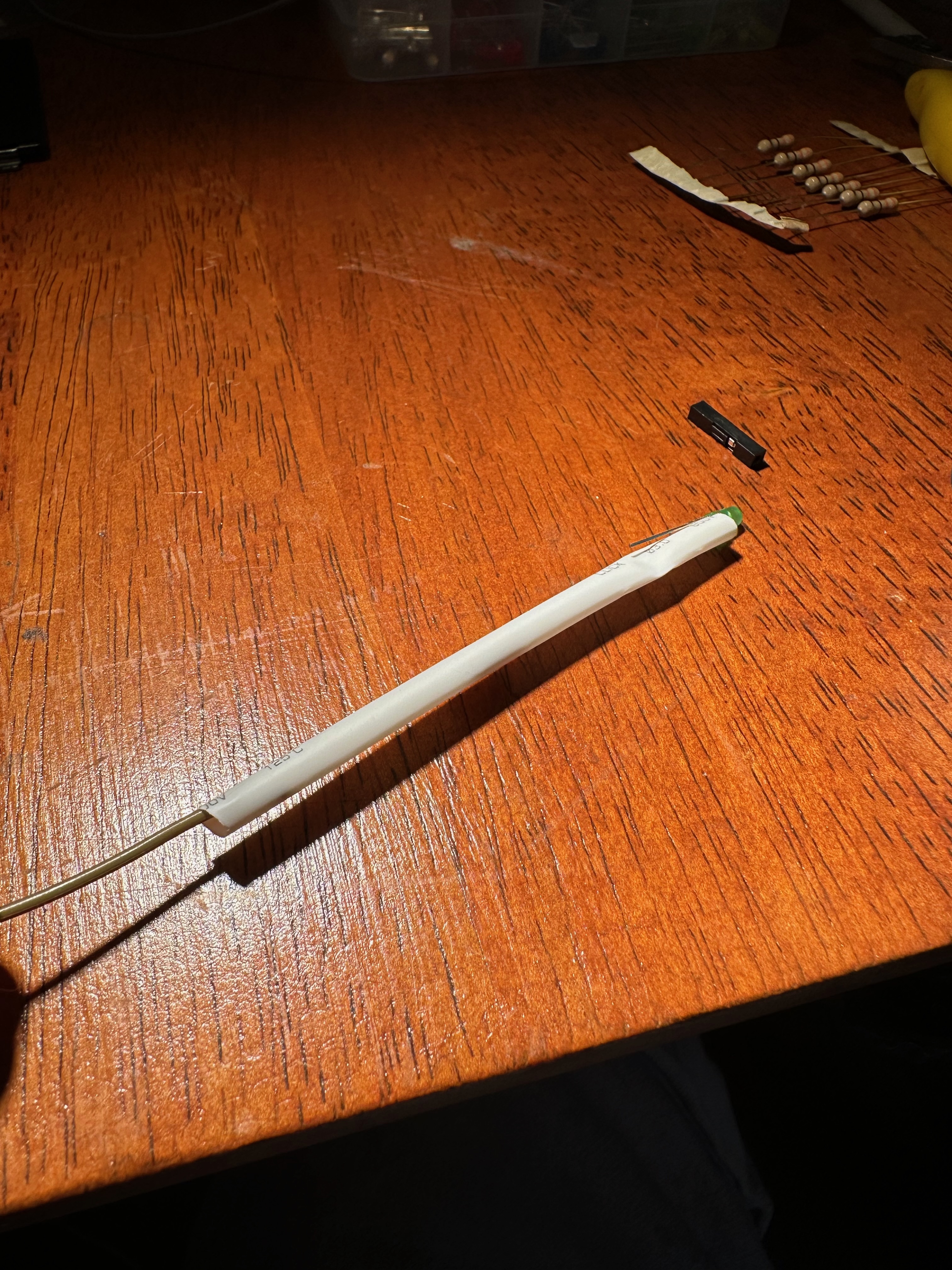
Figure 9: Solder the cable to the LED assembly.
Step 10 – Inspect the wiring
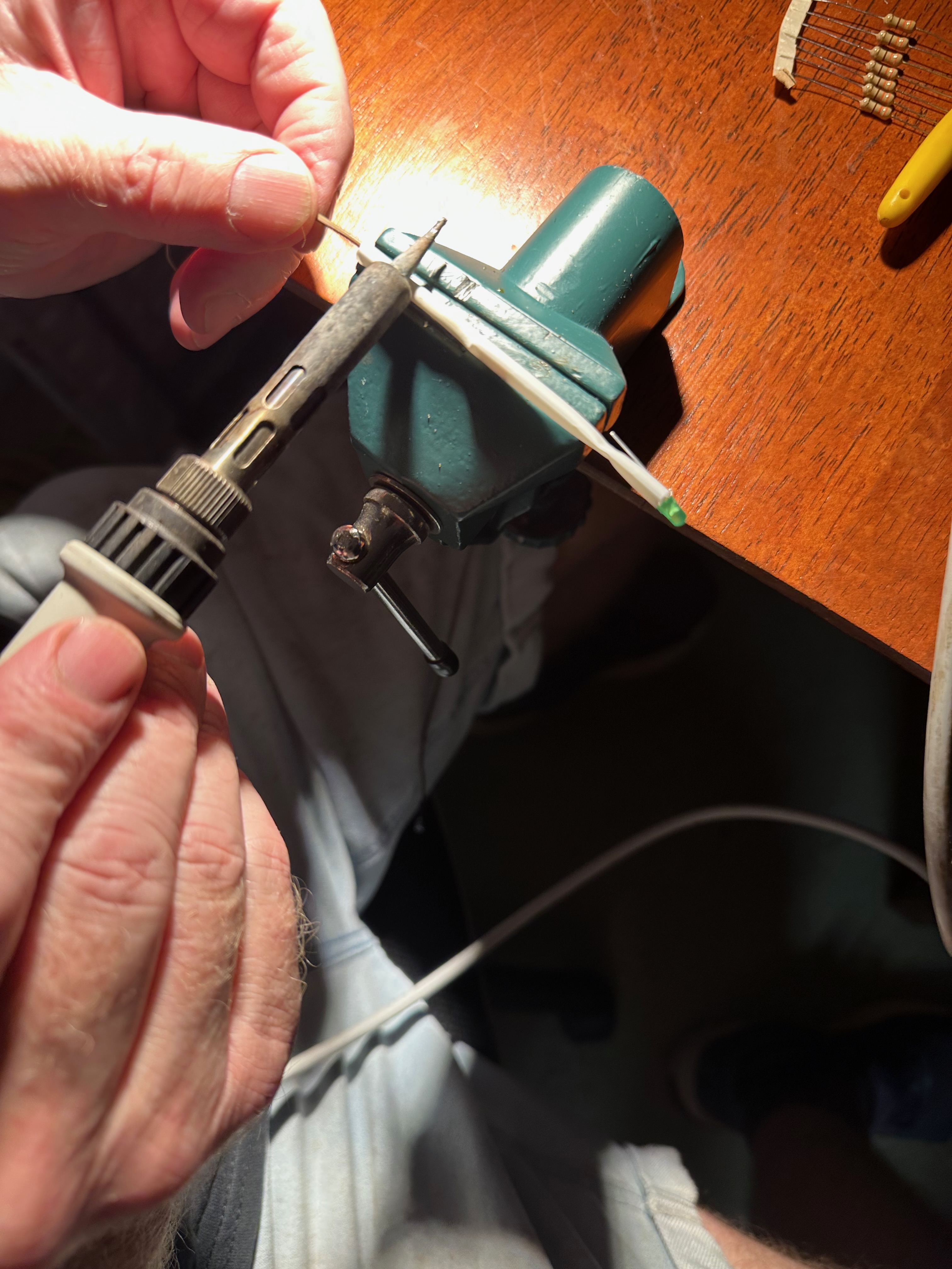
Figure 10: Check the polarity and quality of all solder joints.
Step 11 – Final insulation
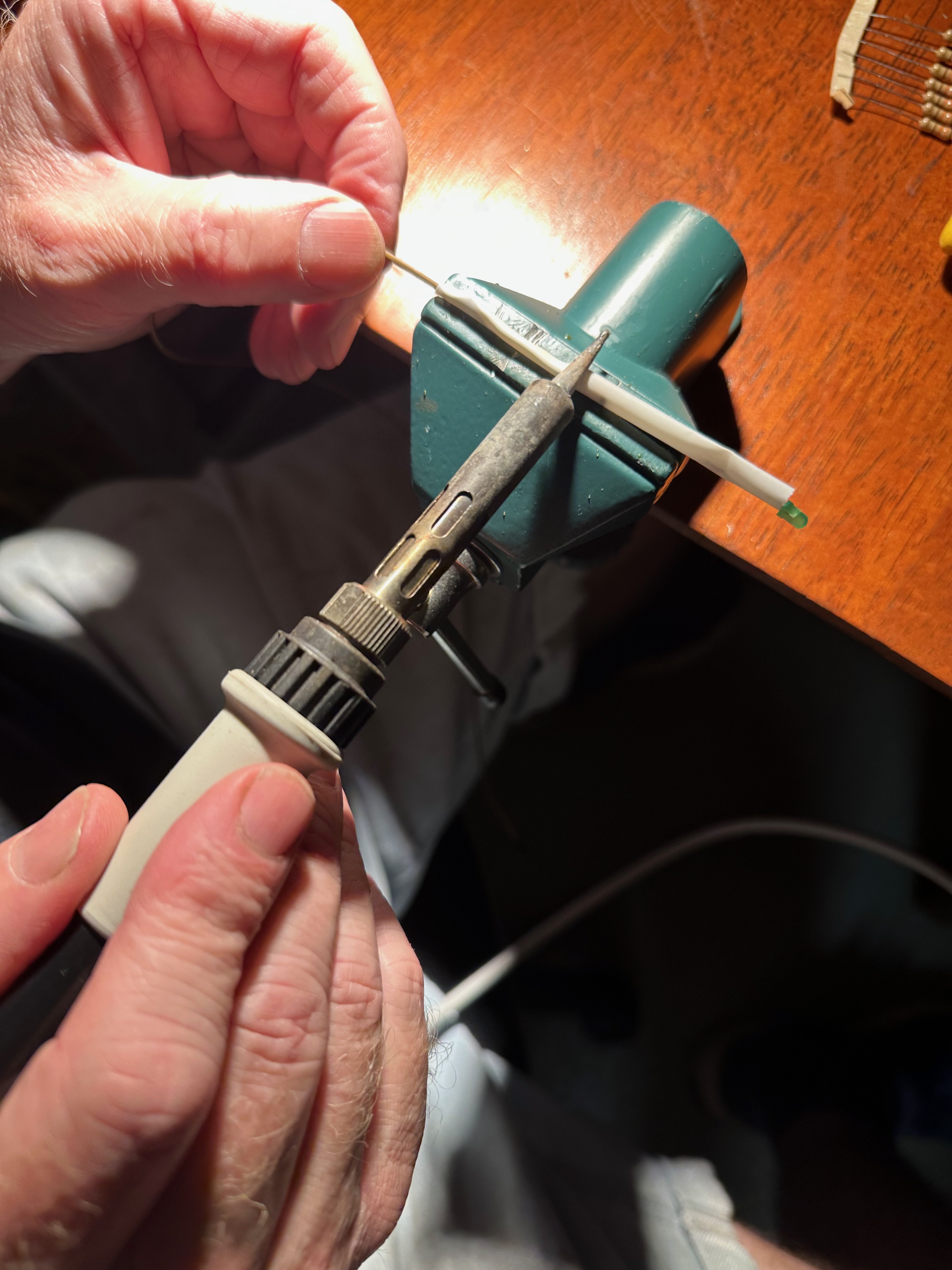
Figure 11: Apply the remaining heat-shrink tubing to protect the wiring.
Step 12 – Check the assembly
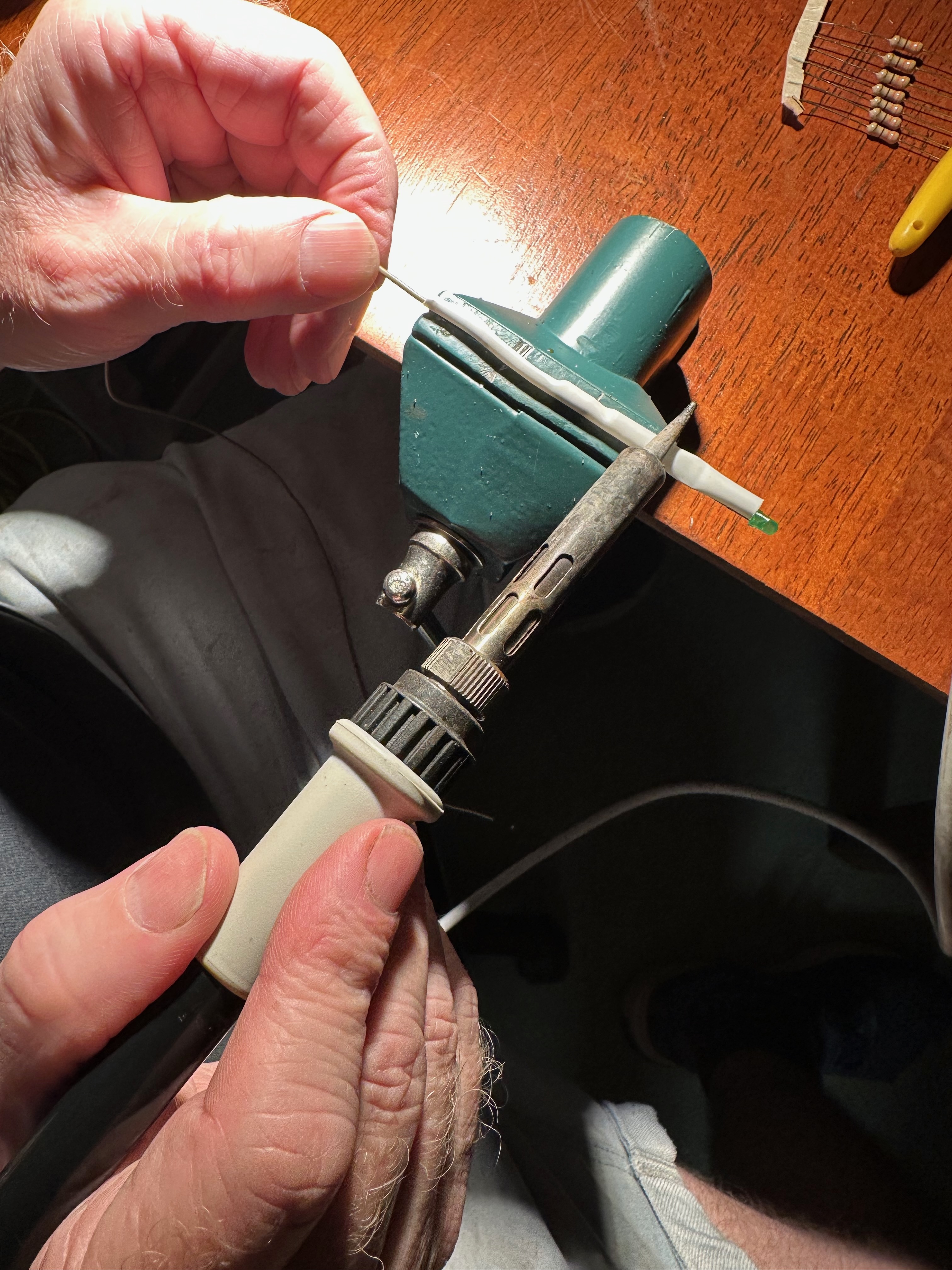
Figure 12: Inspect the completed LED assembly for correct workmanship.
Step 13 – Test the LED
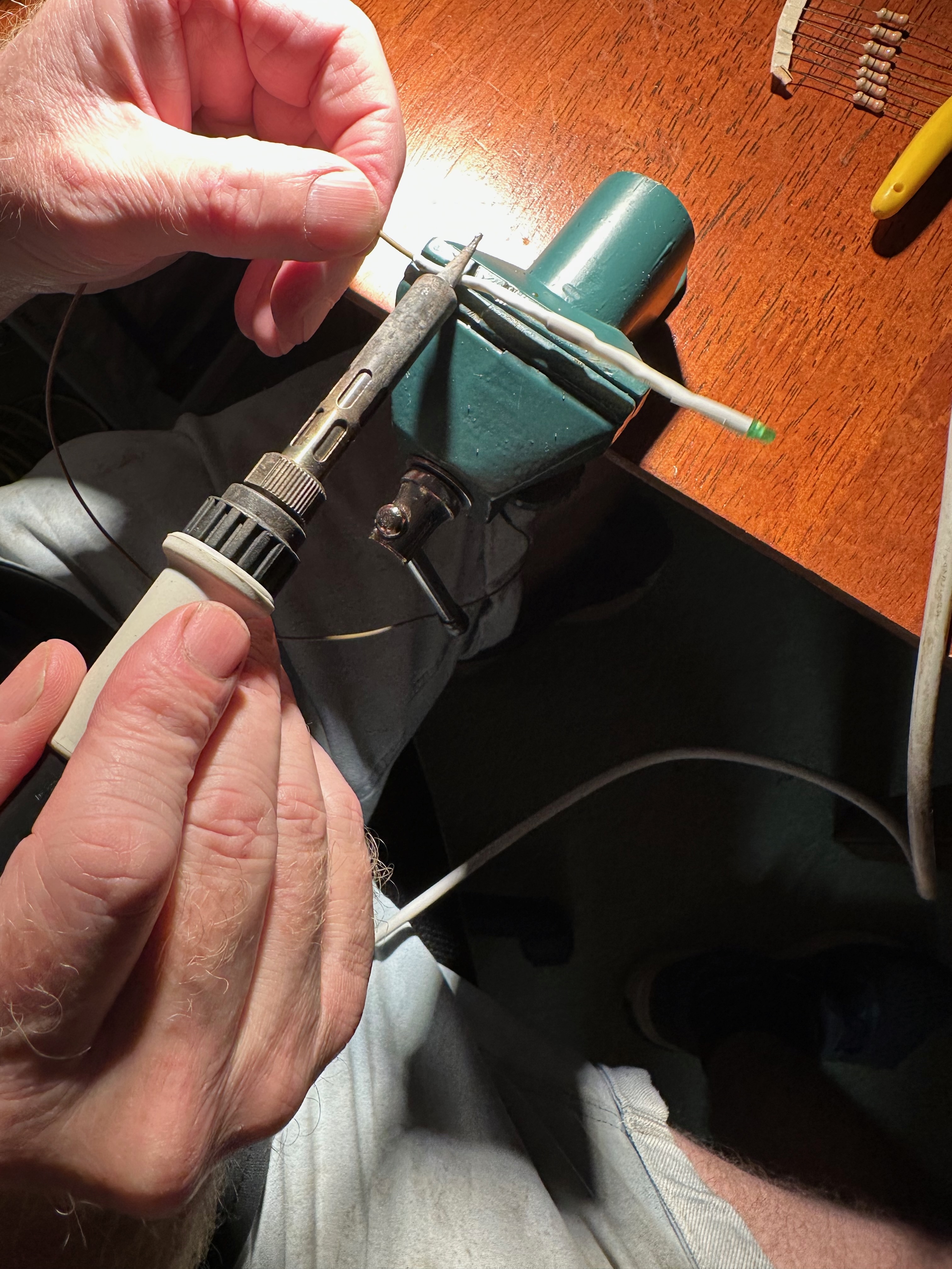
Figure 13: Verify the LED operates correctly before installation.
Step 14 – Ready for installation

Figure 14: The completed LED assembly is ready to be fitted to the chassis.
Step 15 – Completed assembly
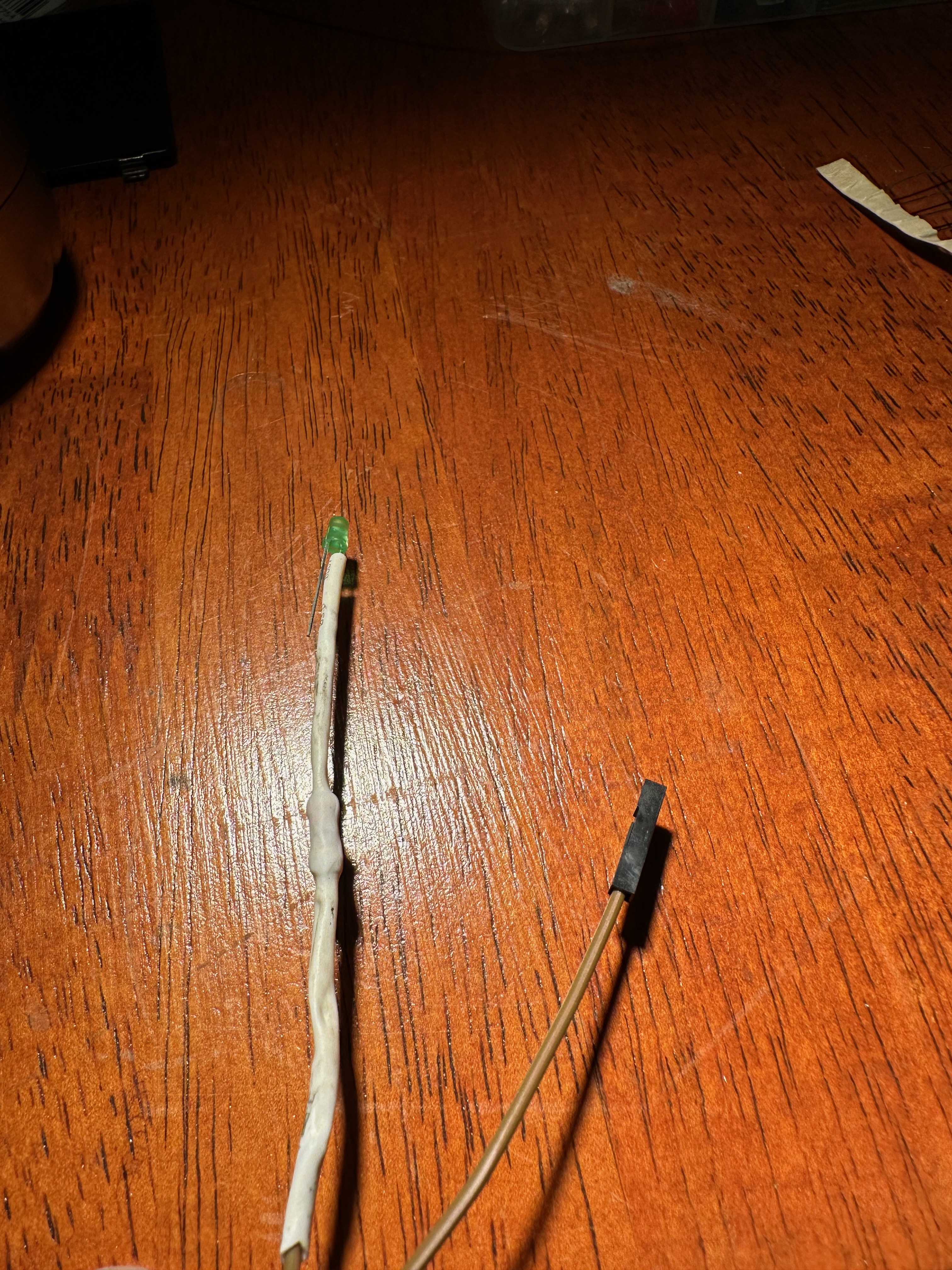
Figure 15: Finished LED assembly ready for use in the Mogwai Drobo NAS.